There's 120'ish mph and 0-60 in 4.2 seconds in there somewhere..!
Electrical Configuration
- Main Loom:
- Loom Configuration
- Engine Bay Wiring
- Boot Wiring
- Relays
- Fuses
- Ignition Switch Configuration
- Power, Connectivity & Distribution
- Wire, Connectors & Terminals:
- Cable
- Connectors
- Terminals
- Solder
- Cable Management
1. Main Loom
I've worked through the looms, and I have identified and labelled all the wires.
I extended some wires to facilitate some changes, modifications and extensions, and I used the correct rating of wire; and where practical, the same colour coding.
For neatness and safety, I also invested in the correct size terminals and heat shrink for the different wire sizes. This is to ensure a proper connection and neaten everything up, and make sure there is no exposed metal or wire, and I've measured the various diameters of the clusters of wires along the loom runs and used a selection of stainless steel "P" clips to support where necessary. I opted for 6 mm, 8 mm, 10 mm and 16 mm clips.
Also, as I went the Speedhut, not the Smiths route for my gauges, some of the dash' loom wiring is redundant. e.g. The Speedhut gauges use a series, feed-through power-and-ground and lighting set-up, and they are all powered from a single switched feed. Also, all telemetry is done using their own specific and individual cable, which connects directly from each sensor to the relevant gauge.
As previously stated, and having gone the EFI route for my Ford 302 (not the carb' route), the sensor-to-gauge hook-up principles were the same, so the amount of head-scratching and fiddling and tea and biscuit interludes were about the same.
i. Loom Configuration: There are three "functional" areas to the car's loom:
- Relays
- Fuses & Multi Plugs
- Boot
a.

b.

c.

ii. Engine bay wiring: I've seen many ways of routing this line of wires, and I've fixed mine to the inside edge of the engine bay, mostly tucked away under the bonnet lip. Then, fixed the remaining o/s wires to and across the bonnet hinge retaining bracket.
iii. Boot Wiring: The wires for the boot, i.e. lights, number plate, etc., are fed in from the tub. Luckily, I didn't need to cut a chunk out of the passenger side cockpit back panel to feed the cluster of loom wires into the boot. There was a small hole going from the boot into the cockpit area at the perfect position, so I fed the loom through and used a piece of heater piping as a grommet.
The wiring diagram shows all the boot hookups for my installation. Notice the double-earth reverse and fog lights [blacks] plugged into the unused earth. This leaves a bunch of wires surplus to [my] requirements. Also, I do not need to use the offside fog and reverse lamp (RY & BN) connections, as these are just extensions from the near-side cluster.
I've also run some independent cabling into the boot, specifically for:
- MSD fuel pump (direct connection from the ECU controller)
- Power (G) from a 12V switched bus for the MSD fuel sender. It requires a direct power feed
- Gnd for MSD fuel pump (25 Amp cable) from gnd bus
- Gnd for the fuel tank and fuel filler (16.5 Amp) from gnd bus
iv. Relays: First, I fixed in place the bank of seven relays. But, I wasn't happy with just self-tapping these to the bulkhead as the surface was contoured, so I mounted them onto a 'raised' aluminium back-plate. This backplate is secured to the side by two mounting brackets and a couple of M5 bolts. A very generous half a day's work, but it was worth it as it is now easy to detach the whole bank of relays as one.
I toyed with the idea of having a bank of 8-10 relays, but there is only enough room for seven [comfortably] in a row. I will need at least a couple more; one for the Pilgrim MotorSports starter button and one for the heated seats.
Made the mounting brackets from a piece of scrap steel bar [A piece of square steel tube would have been perfect, but I didn't have any].
Each bracket consisted of a couple of 10 cm lengths of steel. The first has an M5 thread tapped into it, and the second an M8 hole. The second piece provides a bit more distance from the inner curved side of the car. The two individual steel fixing bracket elements were epoxied together and fibreglassed high up in the passenger footwell, and the relay back-plate was bolted in place (with the relays bolted onto it). Everything ended up flat and level and secure and is now easily detachable... job done.
Relay bracket in place (with relays mounted) and looking quite neat

I also made a secondary relay mounting bar/bracket to take four additional relay units. This is for the 40-amp starter button relay and the heated seat relay, which leaves a couple for future use. Notice also that the 50-amp master fuse holder is on a metal backplate. Am really not a fan of having electrical congestion spots in direct contact with GRP or plastic.
Relays Configuration:

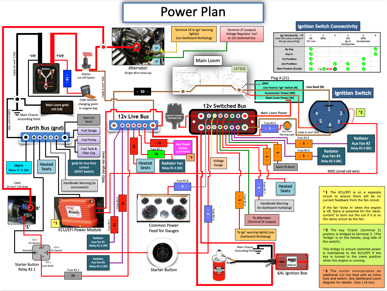
Bus Bars
The two bus bars (just below the heater outlets) are for the common distribution of 12v live and grounds. The 12V switched bus is located behind the dashboard. This keeps all the 'same' in the same place.
Buses are:
- 12v Live: To a 5-pole bus bar in the passenger footwell
- 12v Switched: The feed is from terminal 4 on the Ign' switch. This is a 10-pole bus bar which is located centrally, behind the dashboard
- Gnd: To a 5-pole bus bar in the passenger footwell
So all of the electrical safety and distribution gubbins are located high up in the passenger footwell area and behind the dashboard.

v. Fuses: I've installed a couple of additional 'stand-alone' eight-way fuse blocks. Figured I'd need more, so it made sense to colocate them alongside the existing integrated fuse bank. Having a second unit in the same place as the original also makes it easier to [electrically and physically] manage.

vi. Ignition Switch (Configuration): I've sourced, from my local scrapyard for a fiver, a proper (female) connector plug for the Vauxhall (male) ignition terminal plug. Here is a functionality and connectivity matrix to illustrate how it connects with the main loom plug (Plug A (21)).

*2 Terminals 2 & 3 are bridged to ensure uninterrupted current over these two terminals
2. Power, Connectivity & Distribution
3. Wire, Connectors & Terminals
i. Cable: The majority of the loom cable consists of just two sizes:
- 16.5 Amp
- 25.0 Amp
Sourced cables for my modifications and extensions. Black, Green, Red, and Purple for power and gnd; and I also sourced proper colour-coded wire to extend other specific coded items, but I used grey for some modifications as it's not a primary electrical wiring convention colour for anything.
ii. Connectors: A pack of Lucas-style bullet connectors came with the main loom and some of the loom endings, and some had brass bullet fixings already crimped on the ends. And having seen how these function, I was not happy as they were very exposed and susceptible to all sorts of environmental influences. And during my efforts to fit them, I had to reshape some of the 'grab' connector sockets to make the bullet-end fit properly... I really was not impressed with the functionality of these, so I changed them to spade connectors.
iii. Terminals: It might seem a bit of overkill to write about terminal sizes, but I found that if the wrong size was used, i.e. if the bit you crimped was too big with respect to the wire size that was being connected, I found the hold on the wire was doubtful. So I bought the correct terminal size for the wire size I was using.
Terminal types and sizes used:
- Spade (Open Barrel Female): (Clear plastic insulating sleeves were used on these, too)
- 6.3 mm: These are for the 25 Amp cable or for when I needed to join two thinner 16.5 Amp wires to the same terminal
- 4.8 mm: For the 16.5 Amp cable
- Male Blade Terminals:
- Blade Width / Cable Size: 4.8mm / 0.5 - 1.5mm²
- Blade Width / Cable Size: 6.3mm / 1.5 - 2.5mm²
- Ring Terminals:
- 5.3 mm hole diameter for cable size 0.5 - 1.5mm²
- 5.3 mm hole diameter for cable size 1.5 - 2.5 mm²
iv. Solder: I restocked from a well-known internet website in readiness for me to join up my car's electron-providing arteries... And it was absolute rubbish... An utter crap product...
It wouldn't take to a wire like the stuff I was just about to run out of, and when I did manage to get it to wick into a wire, it dried with a milky, hazy surface; not a shiny one as I'm used to... I was not happy with this at all. And this milkiness could be attributed to a couple of things:
- Lead-free solder: This was not the case, as it was not lead-free, so I discounted this as being the cause. Note... I didn't go the lead-free route because there is a greater risk of it not creating such a good electrical connection... Lead in solder is a good thing.
- Poor quality solder: I'm going with this one... Don't know why it was so crap, and I have no way of finding out, as it's in the bin.
So... having dumped the milky stuff, I sourced some very nice shiny 60:40 tin/lead solder locally, and it was a pleasure to watch it flow and caress the chestnut-coloured intertwined tentacles of copper; it congealed sedately and serenely, creating a very shiny and very conductive joint... (I really need to get out more!)
4. Cable Management
"Out of Sight" is really not "Out of Mind" since cable management not only makes things look good, but it is practical for troubleshooting and safety reasons too... It's also very relaxing and therapeutic... (And an IVA requirement.)
- When fixing the connectors, I used heat shrink (the type with the inner adhesive lining) after I wicked some solder into the crimped joint... Total over-engineering, but I'm happy with the outcome
- As I've routed my front lights wiring and the engine loom along the inside of the engine bay, there is no possibility of the joints getting sprayed with water or muck from the wheels, but I did replace all bullet connectors with covered spade connectors
- I also put PVC cable sleeving on all exposed wires, e.g. the two wires from the front indicator lights are now all contained within a single protective PVC sleeve
- The only exposed connections are the earth bullet types on the front indicator lights... Not sure what I'm going to do to protect these from the elements yet
- When crimping ring terminals, I found the insulation tended to split, so I took these off and replaced them with adhesive heat shrink. Not too big a job, and it allowed me to wick a drop of solder into each joint as an added holder and conductor.
More Photos in the Photo Gallery